Relevant types of combustion prime movers are subject of this work package. The state of the art of current
technical development is described in brief, including DF and Gas applications. The work package will also cover
fuels cells and gas turbines. A special focus is also given to alternative fuels related to these prime movers.
For the shipbuilders this is the base to determine the possible developments with regards to technical
development, reduction of lifecycle cost and further reduction of fuel consumption and emissions.
Regarding the types of engines, certain types are better suited for certain applications i.e. certain transport
tasks and thus certain ship types.
LNG as a fuel with a high potential for clean emission ships and efficient conversion of chemical into kinetic
energy shall be described as well as the application of different types of fuel cells.
This document contains also an evaluation of the current fuels as well as the fuels which have a large
potential for future applications such as Bio Fuels.
Total investment costs must also be subject to the evaluation in JOULES. This report lays the base for such an
evaluation.
State of the art propulsors
Propulsion to overcome the resistance of the vessel is part of this work package. The resistance and resistance
optimisation is outside the scope of this work package. The propeller is an important part in the overall energy
consumption of a vessel. From the perspective of the overall energy consumption the propeller efficiency is defined
as the power effective power of the ship (without propeller) divided by the propeller power. The efficiency is in the
range of 0,5 to 0,7 related to the overall ship resistance.
Today the main propulsors used on ships are e.g.
- open propellers
- controllable pitch propellers
- propellers in nozzles
- steerable thrusters
- podded propulsiors
- counter rotating propulsors
- ultra large propulsors.
The selection of propulsors is to be based on the needs of the specifics vessels operating profile and main
characteristics. The main choice is heavily dependent on the following facts:
- Operating profile such as free sailing operating versus manoeuvring characteristics.
-
Drive train characteristics and capabilities (for instance when a diesel electric variable speed drive is
used reversing allows a simple fixed pitch propeller to be used)
It should also be noted that the choice and number of propulsors may affect the appendages needed behind the
ship. This also has an effect on the design freedom for the hull and the appendage drag and should be considered in
the overall performance predictions. All in all the propulsor selection determines to a large extend the overall
propulsive efficiency.
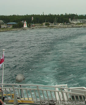
Fixed pitch open propellers
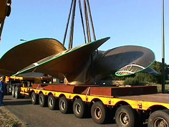 Figure 1 - Open fixed pitch propeller on transport
Open propellers are the most normal type of propulsion for seagoing vessels. The design is optimised to fit the
vessel whereas normally the maximum propeller to fit a vessel is in the order of 70% of the draught aft. This may
depend on vessel type.
The layout of the fixed pitch propeller needs to be tuned to the driving machine. In case of a gearbox or an
e-motor this is simpler, then in combination with a two stroke diesel engine with a direct drive.
Matching the number of revolutions means finding the number of revolutions which given the highest efficiency.
A lower revolutions will increase rotational losses whereas higher implies more frictional losses.
Today many optimisation methods include variations in blade tip shape such as tip rake or Kappel shapes just to
get the highest possible efficiency. These will be considered when needed in this work package.
Controllable pitch propeller
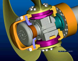 Figure 2 - Controllable pitch propeller
For vessel which have multiple operating condition for instance free sailing and towing,, it may be difficult
to have the maximum power output in all operating conditions. This can be achieved using a controllable pitch
propeller where the pitch can be adjusted in any operating condition (Figure 13). The application of such systems
enables full power absorption in any operating condition(and ship speed).
Today several makers offer controllable pitch propellers which are commonly used in combination with 4 stroke
diesel engines and gearboxes. Through the year the size of the hubs have become smaller due to better design methods
and better materials. The pitch is changed via a hydraulic actuating system inside the hub. The change in pitch needs
to be well tuned and controlled in combination with the engine governor in case of 4 stroke engines. Combined
operation of propeller and engine will give best operating points for every operating condition.
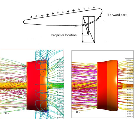 Figure 3 - Working principle of the nozzle propeller
The idea of surrounding a propeller by a nozzle is already dated. In the early 1930’s the ducted marine
propeller came into practical use, stimulated by experiments by Ludwig Kort and others. It then appeared that an
appreciable gain in bollard pull could be obtained. Obviously, specific ships do benefit from the application of this
device, such as tugs, icebreakers, push boats, supply vessels and trawlers. However, also other ships sailing at low
to moderate ship speeds (indicative speed range between 15 and 20 knots) can benefit from the use of nozzles.
To illustrate this: today about 25% of all controllable pitch propellers are running in a nozzle. It is for
this reason that many suppliers have contributed to the development and design of ducted propellers as shown in
various newsletters and publications.
The working principle of the nozzle propeller can be illustrated with Figure 14 showing streamline patterns for
different operating conditions.
Figure 3 - Working principle of the nozzle propeller: forces acting on nozzle profile (top) and flow pattern
around the nozzle propeller system for bollard condition (bottom left) and free sailing condition (bottom right).
In an accelerating nozzle which is the normal used type nozzle, the water speed at the propeller disk is higher
than that of the open propeller. For accelerating nozzles the increase in axial velocity reduces the propeller load
especially for heavily loaded propellers. This then leads to an increase in overall performance of the propeller and
nozzle compared to that of a propeller alone. Additionally, the nozzle generates forward thrust caused by the
pressure distribution around the nozzle, resulting in a force in the forward direction and a compression force acting
in the radial direction.
 Figure 3 - Working principle of the nozzle propeller
An accelerating flow due to the nozzle reduces both thrust and torque at the propeller for given pitch. In
order to get the same power as an open propeller the propeller in a nozzle requires a larger pitch. This is the
reason why propellers in nozzles require larger pitch angles then open propellers. This is aggravated by the fact
that the optimum diameter of a propeller in a nozzle is smaller then that the corresponding optimum diameter of a
propeller without nozzle. Without influence on the power of the propeller, the nozzle will contribute as much as the
propeller to the total thrust. For equal power, the bollard pull may be improved by 20 to 30 percent. Today several
makers provide nozzles shapes with claims for better operation in various conditions.
The nozzle needs to be integrated and connected to the hull to achieve robust and reliable performance. In many
cases a semi tunnel is used to integrate the nozzle into the ship (Figure 15). Nozzles are applied on dredgers and
nowadays increasingly for general cargo vessels up to ship speeds of 20 knots.
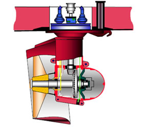 Figure 4 - Steerable thrusters arrangement
Steerable (azimuth) thrusters refer here to those propulsion systems that can generate thrust vectors in a
horizontal plane in any direction by rotating the propulsion unit around its vertical shaft continuously with
delivered steering moments, installed with propellers of conventional controllable pitch blades (CPP) or fixed pitch
blades (FPP), with open or ducted propellers, with tandem or counter-rotating propellers (CRP), in a pulling or
pushing configuration. Water jets; pump jet or Voith Schneider propulsion systems are not in the scope of the
following discussions.
The concept of steerable thruster is not new. The first steerable thruster was launched more than 50 years ago.
The original idea was not more than to increase the vessel’s capability in order to manoeuvre in confined waters. In
the early stage, steerable thrusters were mainly used by small working boats. The increasing demands in the last few
decades for dynamic positioning (DP)/dynamic tracking (DT) in the offshore industry led to a strong development of
the steerable thrusters. Especially when the diesel-electric drive concept was widely accepted and large frequency
controlled AC E-motors became available, this development was further stimulated.
Besides that the traditional concepts are made more robust and reliable nowadays, new concepts are being
developed and are becoming available very fast. The most obvious developments are the application of all kinds of new
nozzles, the application of tandem or counter-rotating propellers, the application of pulling system instead of the
traditional pushing system, etc. More distinct is the invention of the so-called podded propulsor, in which the prime
mover is an E-motor, installed in the underwater housing, driven directly the propeller without gears.
The large varieties of thruster concepts now available in the market provide the yards and the ship operators a
lot of possibilities to choose the most suitable system for their specific purpose of operations, in order to fulfil
a certain type of work.
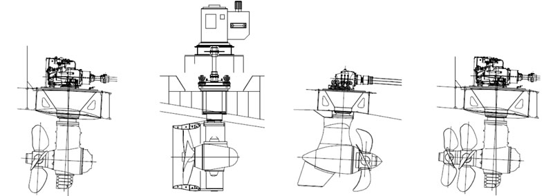 Figure 5 - Steerable thrusters concepts
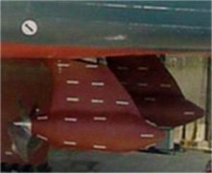 Figure 6 - Podded propulsion system on a cruise vessel
Within the past 20 years, Pod Drives (propulsors with outboard electric motor) with a power of up to 21 MW per
unit have been developed and put into service; especially for large cruise Liners, but also for Ro-Ro-ferries and
supply vessels and ice breaking vessels. The success of Pod Drives is due to several advantages that they have over
the conventional, shaft drive arrangement, like:
- Better manoeuvrability
- Lower noise generation
- Potential for more payload, because the constraints on the machinery layout are less severe.
- More freedom in choosing the location of the main engines.
The question of the hydrodynamic efficiency of pod drives has played an important role in many discussions.
However when a diesel electric power system is selected the electrical pod system may be selected as well. Today 50%
of the cruise liners have podded propulsors.
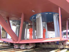 Figure 7 - Cycloidal propeller also called
Voith Schneider Propeller
For vessel which have multiple operating condition, for instance free sailing, towing and manoeuvring, it may
be difficult to have the maximum power output in all operating conditions. Cycloidal offer this solution. The product
name is Voith Schneider Propellers (VSP) are used primarily for ships that have to satisfy particularly demanding
safety and manoeuvrability requirements. Unique to the Voith Schneider Propeller is its vertical axis of rotation.
The thrust is generated by separately oscillating, balanced propeller blades. Due to its physical operating principle
and its design, thrust adjustments can be done very quickly. The VSP, a controllable-pitch propeller, permits
continuously variable thrust adjustments through 360°; combining steering and propulsion. Rapid step-less thrust
variation according to X/Y coordinates improves ship handling. Voith Schneider Propellers operate at a comparably low
revolution speed. Currently, VSPs are used primarily on Voith Water tractors, Offshore Support Vessels, Double-Ended
Ferries, Mine Countermeasure Vessels and Buoy Layers.
Counter rotating propellers
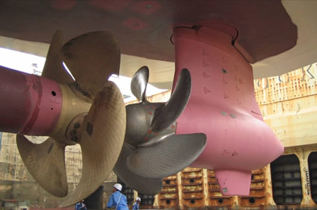 Figure 8 - Counter rotating propulsion set up
The knowhow on counter rotating propellers is based on a equal power distribution between forward and aft
propeller. These systems have been studied and reported in references in the early 70‘s and been applied to a few
Japanese cargo vessels indicating overall efficiency improvement of 15%. This saving consists for almost 50% of an
increase in hull efficiency. There is no explanation for this effect. Probably the more even distribution of thrust
and less suction on the hull due to the split of thrust on the two propellers reduce the thrust deduction. This is
however not supported by theoretical or numerical calculations. The downside of the CRP system is that it requires a
delicate mechanical system at large cost which gives a payback time for around 7 to 10 years dependent on operating
profile, ship type and fuel price.
To improve the payback studies have been undertaken to reduce the power on the aft propeller. The electrical
drive part could be aft. By taking an independent propulsor the mechanical systems is simplified. Studies show that
unequal power distribution will reduce the maximum power saving to about two third to that of the value with equal
power split. (Maximum about 10%). The concept based on independent propulsor but in a counter rotating concept has
been applied in practice. Such a concept now has been applied to a ferry in Japan. The aft propulsor could be a pod
or steerable thruster. Normally such applications are more expensive. However due to the fact that this system
replaces a twin propeller installation the cost increase is limited. The authors report a saving of 13% compared to
the original installation mainly due to the reduction of the appendage resistance caused by the external shafts.
The characteristics of the combined system can be modelled the same way as with a conventional system, provided
that the power split or torque split is given between the two propellers. This may not always be obvious for such
applications.
LAP - Large area propellers
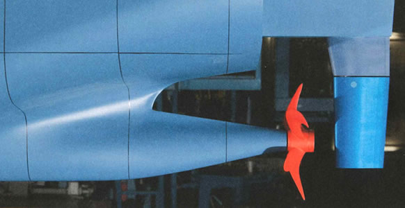 Figure 9 - LAP - Large Area Propeller concept
It is well known that in order to increase the efficiency of a propeller the increase of the propeller is the
most effective ways. New concepts exploring to use ultra large propellers have focussed on two ways to do this:
- The use of large movable fins either mounted vertical or horizontal
- Ways to increase the size of the propeller behind the ship
There is in both cases not so much worries on the basic hydrodynamics of these concepts. The real challenge
lies in the mechanical concept. Being simple and robust is a requirement to even consider such options. Fins for
reasons of mechanical complexity are step by step being developed and may be a solution on the longer term. This
development is followed but not seen as a potential for quick adaption within the Joules project.
Recently the results of another kp7 EU project have been released. This is the LAP large area propeller
concept. A case study based on model test has been carried out for a bulkcarrier and showed between 6 and 17% gain
dependent on the vessel speed.
Challenges in the concept are the fact the propeller is below the baseline and there is a greater (not
specified) risk of propeller ventilation in waves.
Consequences for overall propulsion and link to resistance prediction
The scope of this work package will contain selection and performance of the propulsors. The size of the
propellers depend heavily on the draught of the vessel and the ship speed as well as the thrust requirements. For
given type of propeller (open, nozzle steerable thrusters) a selection can be made on the initial size.
The models will be based on given values for thrust, ship speed and diameter which show the best efficiency
point and number of revolutions. For off design conditions polynomial representations of so called open water curves
can be derived. These will be based on available series propellers but with suitable corrections factors to account
for effect of housing and blade design.
- Input: thrust, ship speed and hull interaction coefficients
- Output: torque and number of revolutions
- Control parameters: number of revolutions and pitch.
The resistance of the vessel will be taken as known. No efforts will be made to the optimisation of hull
resistance within the scope of this work package. Only the effect of trim on resistance will be studied.
The effect of the change in appendages will need to be indicated. Effect of brackets and rudders needs to be
accounted for at least in simplified form.


